
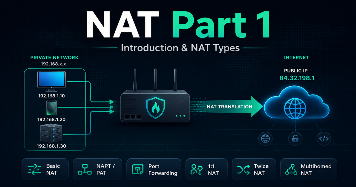
Chapter one – Introduction & NAT Types
Introduction
NAT (Network Address Translation) is a networking feature for translating IP-addresses into other IP-addresses by modifying network information in the IP-header of a packet while they’re in transit across a routing device. The most known example is the commonly known Network address & Port Translation (NAPT). The inclusion of port translation made it possible to not only translate IP-addresses, but also entire TCP/UDP-sessions. If we look at the following topology:
Let’s say I’m on my computer and I want to go to the web page of https://gklablocal.com
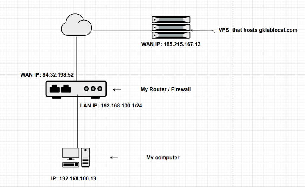
Since the IP of my computer belongs to the “Private IP”-range, it won’t get routed on the internet. So what needs to happen is that my private IP needs to be translated to a public IP. The WAN IP from my router can be used for this.
We’ll go further into detail but in this case what would happen is:
My computer would create an IP packet, with a random source port and 443 (https) as the destination port. The destination of the packet would be the IP of the website itself.
From the moment my packet traverses my router, NAT shoots in place and the following happens:
The packet before NAT was:
Source IP: 192.168.100.19
Destination IP: 185.215.167.13
Source Port (random): 55195
Destination Port: 443
After NAT, the only thing my router would change in order for the packet to be able to traverse and be routed on the internet is the Source IP: after NAT it becomes: 84.32.198.52. My router however needs to remember that the computer is in progress of making a browser session with the website, so it keeps the information (also known as STATE) in its NAT table: it will say:
I have a session in progress for my LAN client 192.168.100.19, I will remember the details so when the packet is returned from the webserver, I know where to forward it to.
Next the packet gets routed onto the internet and arrives at the webserver. There is no inbound NAT defined at the website side so my website replies with the information that leaves the server as:
Source IP: 185.215.167.13
Destination IP: 84.32.198.52
Source Port: 443
Destination Port: 55195
When the traffic returns to my router, the router can match the packet with my session (using the destination port but also the source IP). The router will say:
I have a session that I can match this returned packet with, I will change the destination IP and forward it to the client)
Return packet that my computer receives:
Source IP: 185.215.167.13
Destination IP: 192.168.100.19
Source Port: 443
Destination Port: 55195

Let’s go further with the introduction:
The network address translation NAT protocol was invented around 1994. In 1994, the main engineers of the internet were already thinking or assuming that the quantity of IPv4 addresses were not enough and were already thinking about possible IPv4 address depletion.
Initially, NAT was seen as a short term solution. This can be read in the original RFC of NAT ( RFC1631 dating May 1994):
“It is possible that CIDR will not be adequate to maintain the IP
https://www.rfc-editor.org/info/rfc1631/
Internet until the long-term solutions are in place. This memo
proposes another short-term solution, address reuse“
The short-term solution however became a long-term solution as it’s still in place to this day.
NAT Types
Basic NAT
With Basic NAT, a block of external addresses are set aside for translating addresses of hosts in a private domain as they originate sessions to the external domain. For packets outbound from the private network, the source IP address and related fields such as IP, TCP, UDP and ICMP header checksums are translated. For inbound packets, the destination IP address and the checksums as listed above are translated.
An example of Basic NAT would be a router with X amount of public IPs and it would use each one per session of an internal client that would want to reach something on the internet or a different network:
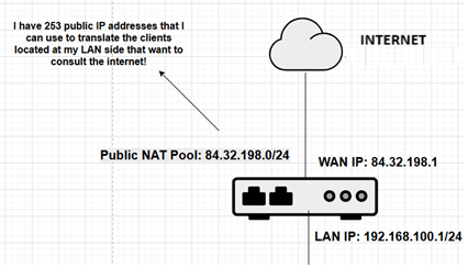
Next it would translate the active internal IP making sessions with public IPs and assign them an address from the pool:
192.168.100.2 -> 84.32.198.2
192.168.100.10 -> 84.32.198.3
192.168.100.11 -> 84.32.198.4
As you might notice, this is not a very efficient way of doing NAT (example: what if the amount of active IPs at the LAN side was greater the quantity of available public addresses?. Basic NAT helps private clients reach external networks, but it is not very address-efficient because every active internal client needs its own public IP address. This is why NAPT/PAT became more common: with PAT, many internal clients can share one public IP address by using different TCP/UDP ports.
Network Address Port Translation (NAPT)
Due to the issues and limitations of basic NAT, they came up with an extension called Network Address Port Translation (NAPT, also called PAT or NAT Overload). The description of this method of doing NAT was described in RFC 2663 which came out in 1999.
NAPT extends the notion of translation one step further by also
translating transport identifier (TCP and UDP port numbers). This allows the transport identifiers of a
number of private hosts to be multiplexed into the transport
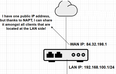
identifiers of one single external address. NAPT allows a set of hosts
to share a single external address. Note that NAPT can be combined
with Basic NAT so that a pool of external addresses are used in
conjunction with port translation:
For packets outbound from the private network, NAPT would translate
the source IP address, source transport identifier and related fields
such as IP, TCP, UDP and ICMP header checksums. Transport identifier
can be one of TCP/UDP. For inbound packets, the
destination IP address, destination transport identifier and the IP
and transport header checksums are translated.
An example of NAPT was mentioned in the introduction of this chapter. But we will mention it again, this time mentioning extra details and add another client:
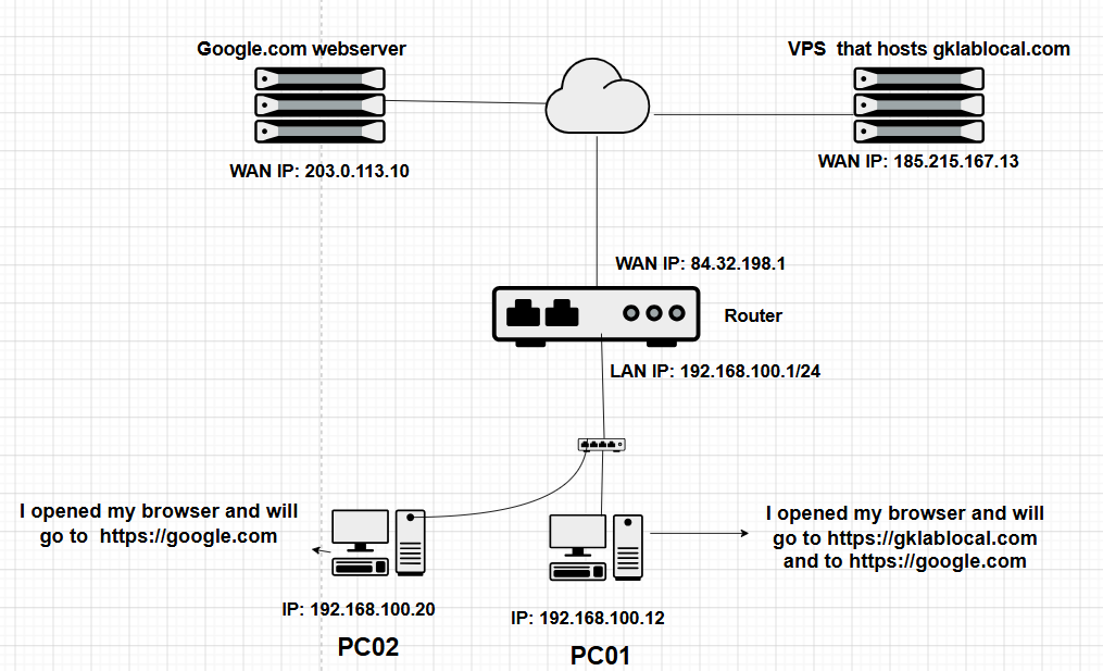
Let’s write down our topology:
Topology
| Object | Value |
|---|---|
| Router / firewall | pfSense |
| WAN IP | 84.32.198.1 |
| LAN IP | 192.168.100.1 |
| PC01 | 192.168.100.12 |
| PC02 | 192.168.100.20 |
| Webserver gklablocal.com | 185.215.167.13 |
| Webserver Google.com | 203.0.113.10 |
Goal
| Client | Action |
|---|---|
| PC01 | wants to browse to the websites of gklablocal.com and google.com |
| PC02 | wants to go to google.com |
We will assume they will do this simultaneously.
NAT Session 1 -> PC01 wants to browse to gklablocal.com
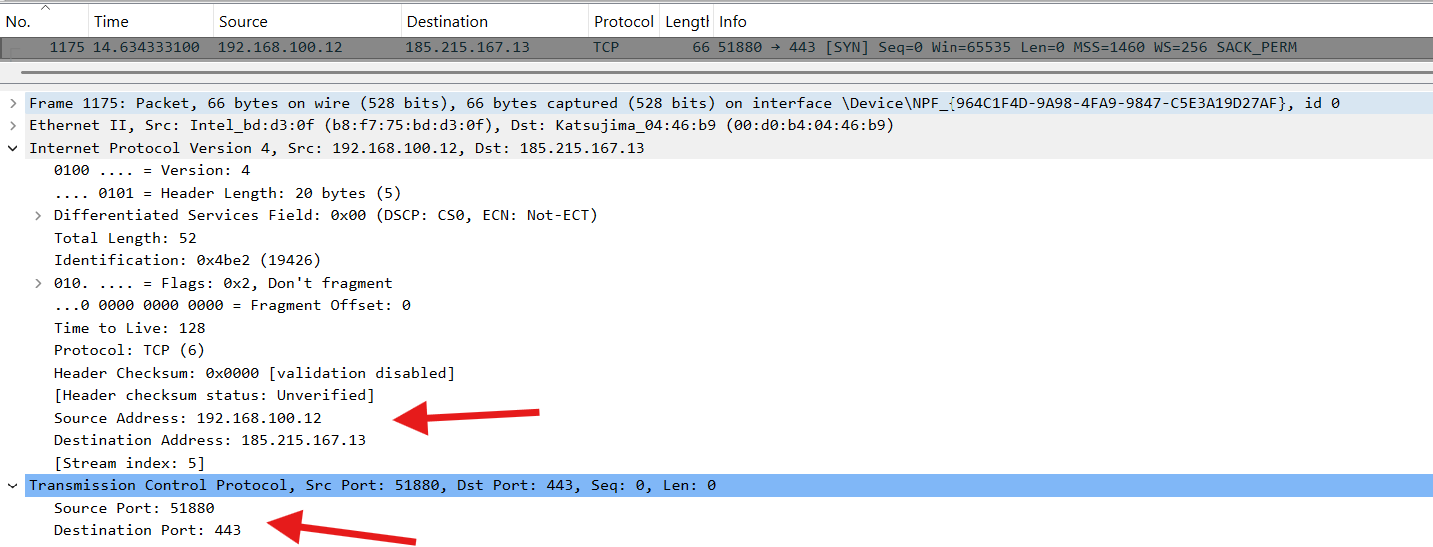
This packet from the moment it leaves PC01 will look like:
| Field | Value |
|---|---|
| Source Address | 192.168.100.12 |
| Destination Address | 185.215.167.13 |
| Source Port | 51880 |
| Destination Port | 443 |
In Wireshark, we can identify the packet as follows:
Next, the packet gets received by the router. The router (in this case a pfSense) will create a STATE in its NAT-table as it needs to remember each NAT-mapping for when the traffic returns, to know where to map it internally to. In pfSense, we can go to Diagnostics -> STATES and filter by my IP:

This is the NAT-table we were talking about earlier where the router keeps the NAT-mappings in memory so that it knows who is doing what, and to know where to forward return traffic to.
The pfSense shows both sides of the same translated connection.
LAN-side state:
This shows the packet as pfSense received it from PC01, before NAT translation.
WAN-side state:
This shows the packet after pfSense translated the source IP address and source port, and sent it out through the WAN interface.
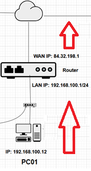
This does not mean pfSense created two separate connections. It is the same connection attempt, shown from the inside and outside view of the router/firewall. The packet now leaves and enters the internet with the following properties:
Source Address:      84.32.198.1
Destination Address: 185.215.167.13
Source Port:         50716
Destination Port:    443
At this point, in the topology the packet is in this stage:
The webserver will receive the packet and reply to it.
When the webserver replies to the packet, it creates a packet that looks like:
Source Address:      185.215.167.13
Destination Address: 84.32.198.1
Source Port:         443
Destination Port:    50716
and the packet is on its way back to our router.
Once the packet is back at our router, our router will match the packet with entries in its NAT-table. it is able to match it with WAN-state we saw in our earlier screenshot, but it’s yet not ready to forward the packet to the PC. What needs to be done is the “last” NAT-operation to get the packet to the PC. Our PC’s IP is not 84.32.198.1 and the source port it used to initiate and send the initial packet was not 50716 (a router can always change or also NAT the source port of a request it receives). What it does is match the initial packet and NAT state to the current return packet and changes it as follows:
Source Address:      185.215.167.13
Destination Address: 192.168.100.12
Source Port:         443
Destination Port:    51880
PC01 receives the return packet and in Wireshark, it’s shown as:
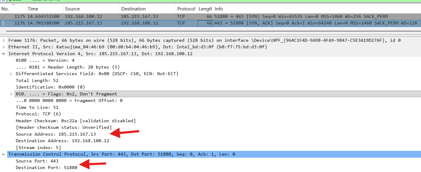
And our session is ESTABLISHED. The PC01 now shows the website on the browser and the user can browse the site.
The pfSense states now look like:

The state remains active while traffic keeps flowing. If there is no traffic for long enough, pfSense expires the state based on its TCP timeout values. A browser may also open new TCP/TLS connections for different objects, tabs, HTTP/2/HTTP/3 behavior, etc. It’s all vendor / browser related (just like how we use the name “STATE” and STATE-Table for pfSense).
Goal #2, PC01 opens a tab in the browser and goes to https://google.com.
In this case we will showcase the importance of the source port:
The destination port will be the same as the earlier connection: 443 (HTTPS). However, the PC needs to select a source port, that is not used in another already existing connection. so it will use again a random port, that’s at that moment unique. The PC01 can not choose 51880 as the source port, because that one is already being used in the established connection with gklablocal.com-browsing session. Normally, the client operating system will choose a different available “ephemeral source port” for the new connection. This keeps the connections easy to track and avoids conflicts. Technically, TCP connections are identified by the full combination of source IP, source port, destination IP, destination port, and protocol.
This shows the importance of the (random) source port in NAPT: thanks to NAPT, one device is able to use multiple sessions of the same destination port (443). The PC is able to open multiple websites thanks to the fact that each connection is unique (but all are using port 443).
We will go to Goal #3, PC02 wants to go to google.com:
Again, this relates to the source port. After NAT is being done we can have multiple NAT-states, using the same public IP but are uniquely identified thanks to the random source port.
Examples for google.com for PC01 & PC02 after NAT:
PC01 chose random source port 56997
PC02 chose random source port 64115
the packets AFTER NAT upon leaving the router (and we assume the pfSense did not change the source ports as it did in our earlier example) towards the internet will look like:
PC01 Packet after NAT:
Source Address:      84.32.198.1
Destination Address: 203.0.113.10
Source Port:         56997
Destination Port:    443
PC02 Packet after NAT:
Source Address: 84.32.198.1
Destination Address: 203.0.113.10
Source Port: 64115
Destination Port: 443This concludes that NAPT caused for a “revolution” in comparison with Basic-NAT, as now ONE single public IP can be used by pretty much a huge amount of internal clients. Although NAPT has its limits as well:
NAPT is not infinite (limited port quantity):
NAPT is very efficient, but it is not unlimited. Because TCP and UDP ports are 16-bit values, there are only 65,536 possible port numbers per IP address and protocol. In practice, not all of these are usable for NAT. Very very large networks can still run into port exhaustion, especially if many clients create many simultaneous connections through one public IP address.
Good for outbound NAT, not for inbound:
In our examples, we always initiated the NAT-“traffic” from the inside (LAN) network towards the internet (aka Outbound-NAT). NAPT works very well for outbound connections because the internal client starts the connection and pfSense can create a state entry. Unsolicited inbound traffic from the Internet does not automatically know which internal client it should go to. To publish an internal service however (let’s say you have a website in your LAN and want to make it reachable from the internet), you usually need port forwarding, static NAT, or a reverse proxy.
This concludes why NAPT/PAT became so important. With Basic NAT, every active internal client still needs its own public IPv4 address. With NAPT, many internal clients can share one single public IPv4 address because the router translates both the source IP address and the source port.
The router/firewall keeps a state table that remembers every active mapping. When return traffic comes back to the public IP and translated port, the router uses the state table to translate the packet back to the correct internal client and original source port.
This is why home networks, business networks, and lab networks can have many private devices behind one public IPv4 address.
NAPT/PAT – Static Inbound NAT / Port Forwarding
With Port Address Translation, we’re able to translate PORT-numbers to different port numbers and also translate incoming traffic on a specific port, to a specific IP-address. This is actually a part of NAPT since there are no RFCs that specify PAT as a separate type of NAT (remember that NAPT is able to translate IPs AND port numbers). Let’s see where PAT comes in place.
PAT is often used in the inbound direction.
Let’s demonstrate with a topology:
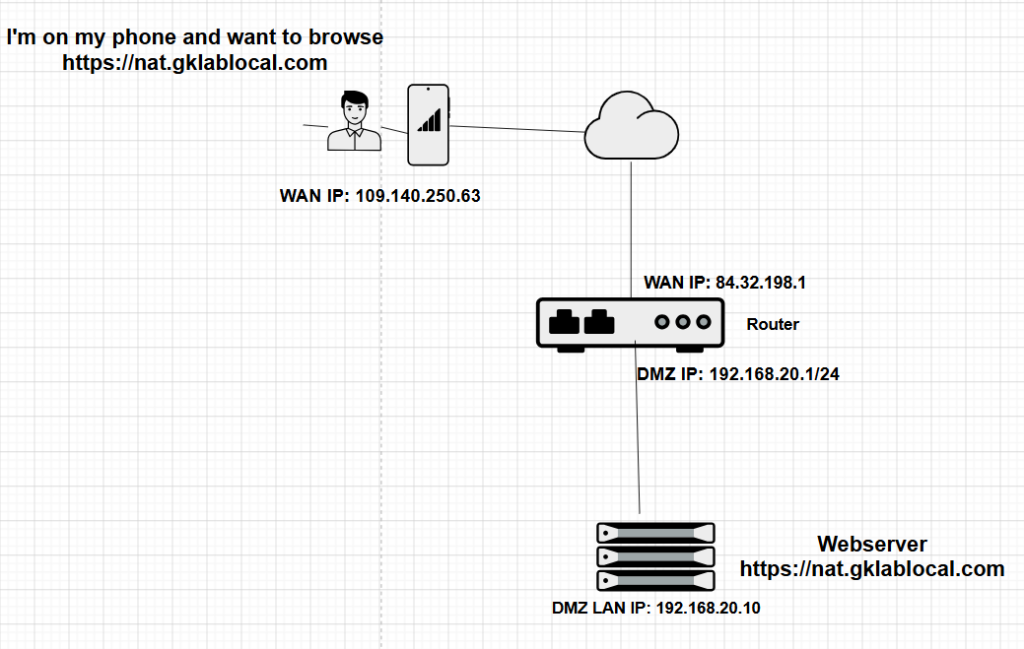
In this case we have the following:
Topology
| Object | Value |
|---|---|
| Mobile phone / 4G client | 109.140.250.63 |
| pfSense WAN IP | 84.32.198.1 |
| DMZ LAN interface | 192.168.20.1 |
| Webserver | 192.168.20.10 |
| Website | nat.gklablocal.com |
Goal
The goal in this case is, we need to tell our router, that all incoming HTTPS requests (port 443), need to be translated/forwarded/redirected to the IP of 192.168.20.10.
At the NAT/port-forwarding level, pfSense does not care about the hostname. It only sees the destination IP address, destination port, and protocol.
Hostnames can become visible later in the connection, for example through TLS SNI during the TLS handshake, or through HTTP Host headers. But that is above basic IP/port-based NAT, and we will keep this chapter focused on Layer 3 and Layer 4 behavior.
In the next part of this series, we will create port forwarding rules in pfSense showcasing the steps in detail. We now assume all is in place.
The person is about to browse the website on his phone:
At the first step, the packet will leave the mobile phone with the following details:
The external client creates the first TCP packet:
Source Address: 109.140.250.63
Destination Address: 84.32.198.1
Source Port: 53122
Destination Port: 443
The packet travels the internet and finds its way to my router, the router will say “i don’t care what website this is, I only know to forward 443-traffic to 192.168.20.10. Hereafter it will perform port forwarding and forward the packet with the following details:
Source Address: 109.140.250.63
Destination Address: 192.168.20.10
Source Port: 53122
Destination Port: 443

!!pfSense changes the destination IP address on the inbound packet but doesn't touch the source!!

That means the internal webserver still sees the real external client IP:
109.140.250.63 (this is ideal in case of logging / tracking website visitors statistics /...)
the webserver will reply and the packet will return back to the mobile phone and after NAT the packet will look like:
Source Address: 84.32.198.1
Destination Address: 109.140.250.63
Source Port: 443
Destination Port: 53122
The entire flow in simple format:
Inbound packet - leaves mobile phone:
109.140.250.63:53122  --->  84.32.198.1:443

After port forward - enters WAN of router and forwards to webserver:
109.140.250.63:53122  --->  192.168.20.10:443

Webserver reply - leaves webserver towards router :
192.168.20.10:443  --->  109.140.250.63:53122

After reverse NAT - router NATs the source IP and sends packet to the internet:
84.32.198.1:443  --->  109.140.250.63:53122
What also is possible is the translation of port numbers (also called PAT – Port Address Translation).
Let’s say I have a website online called https://demo-nat.gklablocal.com. I do not want to publish the demo site on the default HTTPS port 443. Instead, I want to make it reachable on a non-standard external port, 8443, and only share that URL with specific people. In this case, I can create a port translation rule that will translate the port 8443 to 443 and redirect it to the webserver.
And to persons I want to showcase my site to, I will say: use this URL to visit my demo site: https://demo-nat.gklablocal.com:8443
and the trail would look like:
Inbound packet - leaves mobile phone:
109.140.250.63:53122  --->  84.32.198.1:8443

After port forward - pfSense receives the packet on WAN, it applies the port forward rule. It translates the destination IP and destination port, then forwards the packet to the internal webserver:
109.140.250.63:53122  --->  192.168.20.10:443

Webserver reply - leaves webserver towards router:
192.168.20.10:443  --->  109.140.250.63:53122

After reverse NAT - router NATs the source IP and port and sends packet to the internet:
84.32.198.1:8443  --->  109.140.250.63:53122
Bi-directional NAT (or) Two-Way NAT
Bi-directional NAT is a static one-to-one mapping between a private IP address and a public IP address.
In a corporate network, this is commonly used for servers in a DMZ. The server keeps a private IP address, but the firewall gives it a public identity.
When traffic comes from the Internet to the mapped public IP, the firewall translates the destination IP to the private server IP. When the server replies, the firewall translates the source IP back to the public IP.
The same mapping also works when the server starts outbound connections. The server may send traffic from its private IP, but the outside world sees the traffic as coming from its mapped public IP.
This is useful when a company wants to publish a server to the Internet, while still keeping the real server inside a private network behind a firewall.
Example:
Company XYZ has a pool of 5 public IP-addresses. it wants to dedicate 1 IP-address (203.0.107.2) for its corporate website xyz.com (also the name of the webserver). the webserver has the private IP 192.168.20.10.
In this case, we have the following:
Topology
| Object | Value |
|---|---|
| Public IP address | 203.0.107.2 |
| Web server IP | 192.168.20.10 |
| Rule type in pfSense | 1:1-NAT rule |
We need to create a bidirectional NAT-rule. In pfSense, this is called a 1:1-NAT rule:
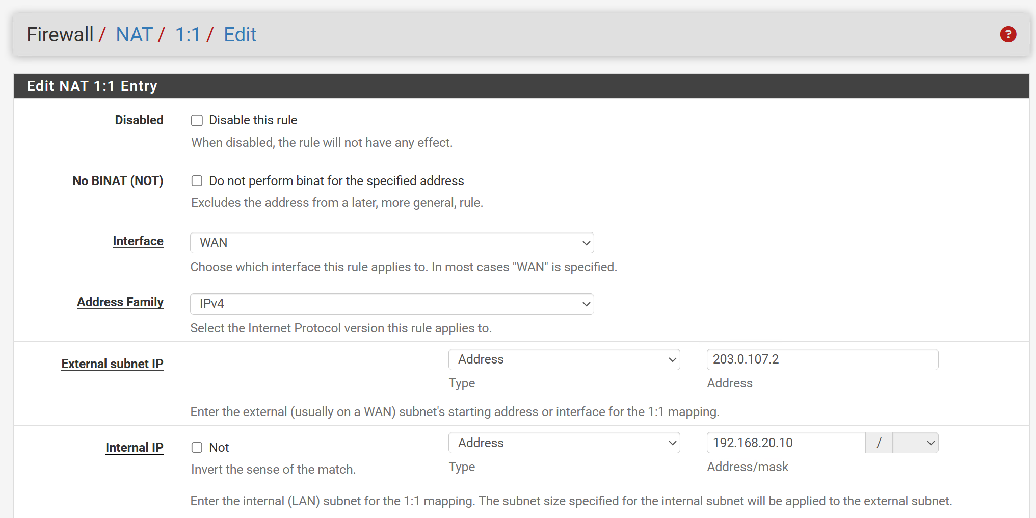
This means in the case of inbound NAT:
When people visit the website, the router will receive the request on a possible separate interface (called WAN_DMZ for example) with the IP 203.0.107.2. It will translate the destination IP address from 203.0.107.2 to 192.168.20.10 and forward the packet to the webserver. And in the reverse NAT (return packet-phase) it will use the WAN_DMZ IP again.
This also means in the case of outbound NAT:
When the webserver is searching and installing updates, its packets go on the internet with the source IP of WAN_DMZ (203.0.107.2).
This gives the following advantages:
- A dedicated public IP gives the server a consistent public identity.
- This can be useful when external partners, vendors, or cloud services need to whitelist the server’s public IP.
- It also keeps the server itself on a private DMZ address, while the firewall controls what inbound traffic is allowed.
- If there is an attack or abuse against this public IP, it can also be easier to identify which internal system is involved, because the public IP maps to one specific private server.
Twice NAT
Twice NAT is a NAT type where both the source IP address and destination IP address are translated in the same packet. In some implementations, ports can also be translated, but the core idea is that both addresses change. You might ask in what case this would be needed or a practical example.
Let’s show where this would be handy:
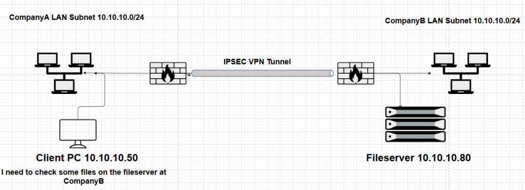
In this example, we have a not uncommon example, where two companies are linked via an IPsec VPN while having the same LAN subnet(!!). This could happen after Company A bought or merged with Company B and by coincidence, they have the same subnet. And guess what: the IT at both sides are not in favor of changing the subnet.
This causes a big issue: let’s say a PC with the IP 10.10.10.50 in Company A wants to reach the fileserver at Company B. It will send a packet, but the router will say “because 10.10.10.80 appears to be in the local subnet, the Company A client will try to reach it locally instead of sending it across the VPN”. It may ARP for 10.10.10.80 on the local LAN, and the connection will fail.
To solve this, we could use “Fake networks” by using Twice NAT:
Company A and Company B have a site-to-site VPN.
Real networks:
| Side | Object | Value |
|---|---|---|
| Company A | Real LAN | 10.10.10.0/24 |
| Company A | Client | 10.10.10.50 |
| Company B | Real LAN | 10.10.10.0/24 |
| Company B | Application | 10.10.10.80 |
Because both sides use the same subnet, we create translated ranges:
| Side | Translated range |
|---|---|
| Company A | 172.16.100.0/24 |
| Company B | 172.16.200.0/24 |
So from Company A’s point of view, the Company B server is no longer reached as:
10.10.10.80It is reached as:
172.16.200.80The firewall then translates it behind the scenes:
Packet flow from Company A to Company B
Company A client wants to connect to the Company B application.
The client sends:
Original packet inside Company A:

Source Address:      10.10.10.50
Destination Address: 172.16.200.80
Source Port:         53122
Destination Port:    443
Simple view:
10.10.10.50:53122 ---> 172.16.200.80:443Then Company A’s firewall performs Twice NAT.
It changes the source:
10.10.10.50 ---> 172.16.100.50And it changes the destination:
172.16.200.80 ---> 10.10.10.80After Twice NAT, the packet going through the VPN looks like:
After Twice NAT:

Source Address:      172.16.100.50
Destination Address: 10.10.10.80
Source Port:         53122
Destination Port:    443
So Company B receives traffic for its real server IP:
10.10.10.80But Company B does not see the real Company A client IP. It sees the translated Company A IP:
172.16.100.50Return traffic
The Company B server replies:
Reply from Company B server:

Source Address:      10.10.10.80
Destination Address: 172.16.100.50
Source Port:         443
Destination Port:    53122
When the reply reaches Company A’s firewall, the firewall reverses the Twice NAT.
It changes the source:
10.10.10.80 ---> 172.16.200.80And it changes the destination:
172.16.100.50 ---> 10.10.10.50After reverse Twice NAT, the packet delivered to the Company A client looks like:
After reverse Twice NAT:

Source Address:      172.16.200.80
Destination Address: 10.10.10.50
Source Port:         443
Destination Port:    53122
From the Company A client’s perspective, it talked to:
172.16.200.80It never needed to know that the real Company B server was:
10.10.10.80We will try and implement this scenario in one of the next chapters.
Multihomed NAT
Multihomed NAT is used when a private network has more than one connection to external networks. For example, a company may have two Internet providers, or two firewalls, so that Internet connectivity remains available if one link or firewall fails.
The challenge is that NAT is stateful. When a NAT device translates a connection, it stores that translation in a state table. Return traffic must normally come back through the same NAT device, because that device knows how to translate the packet back to the correct internal client.
If the outbound packet leaves through NAT Router 1, but the reply packet comes back through NAT Router 2, NAT Router 2 may not know about the connection. It does not have the original NAT state, so it cannot correctly translate the return traffic. This can break the session.
To make multihomed NAT work properly, both NAT devices must either share state information, use a failover/high-availability mechanism, or use static NAT mappings that are configured the same way on both devices.
In simple terms: multihomed NAT gives redundancy, but the NAT devices must agree on who owns the connection state.
In pfSense, in HA-mode, you can select / opt for syncing the STATE-table between devices but this is very resource-intensive of course and even prone to possible issues.